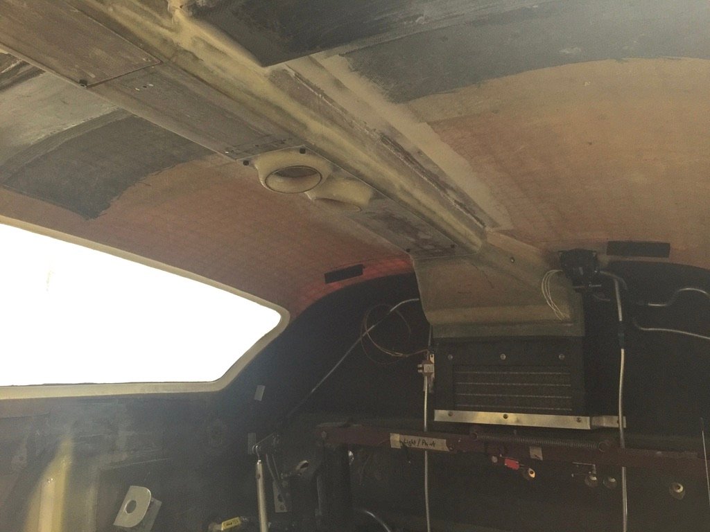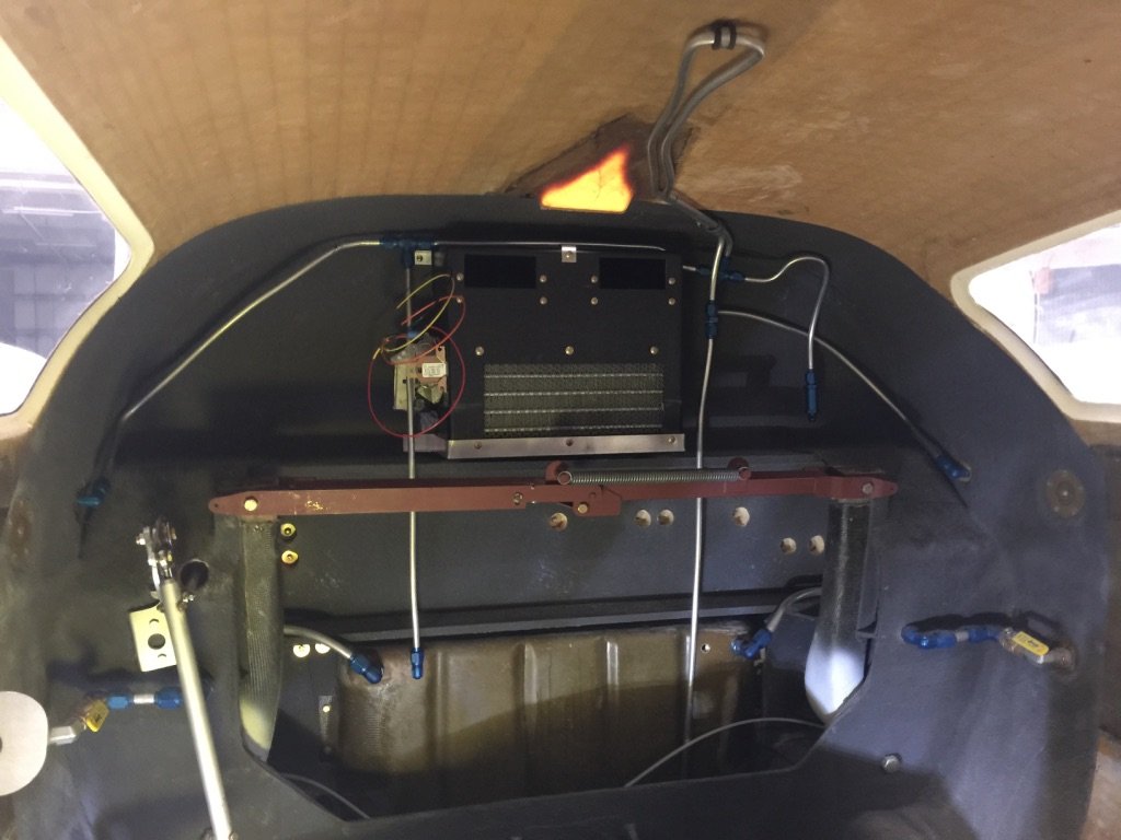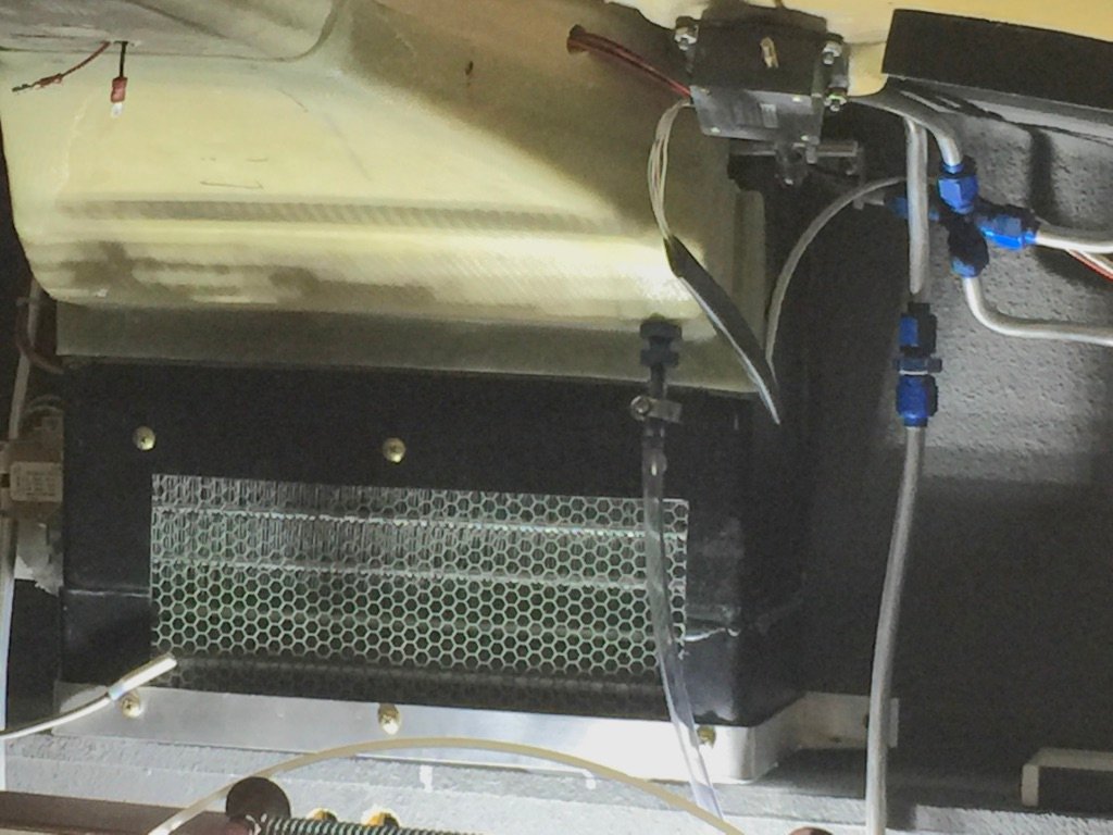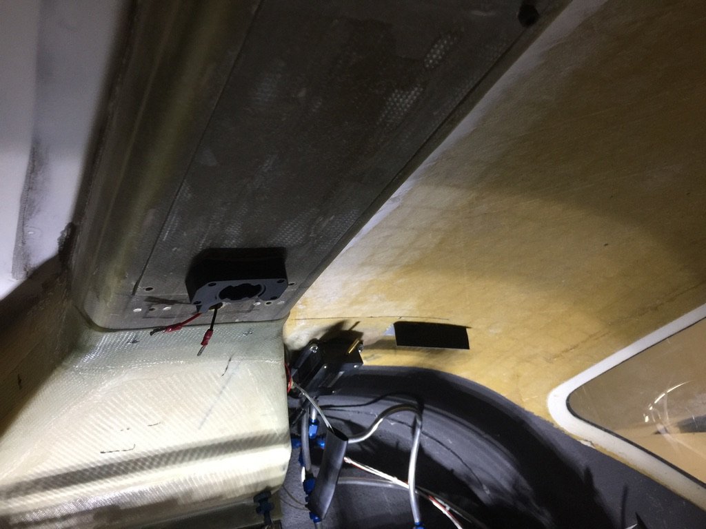
I got all the parts from Flight Line AC, a Kelly Aerospace company.

Since I was told that other builders had not had much success with ac installation efforts, I researched what they had tried, as well as, what kinds of systems might be available. I even looked at building my own custom system from off the shelf parts. I did conclude that some of the previous efforts were lacking in that they employed systems with insufficient BTU’s for the cabin size. There were also issues with inadequate distribution of the cold air.
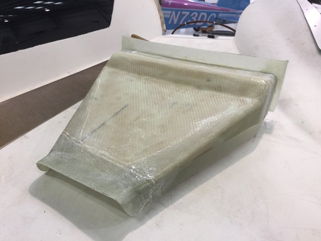
After much research, discussions, and head scratching, I decided to go with a system from Flight Line AC. I chose them because of their success with Lancair IV installations. The Lancair IV has a similar size cabin. Based on my research, I already knew that this project was going to be rather challenging. Since Velocity didn’t have a solution for my AC project, I thought I was going to be pretty much on my own to get this done, but Scott Swing stepped up and helped me make component location decisions along the way, design and make custom mounting brackets for the “Hot Box”, and so on. Also, Bryan McCartney helped me with the wiring (the controller, evaporator, and condenser), Freon hoses, and final installation. Plus, Riley Swing helped me make an enlarged overhead plenum (suggested by the interior installer, Justin), and custom mounts for my eyeball vents. And finally, Ueli Christen made a nice fiber glass piece to transition the output air up into the overhead plenum. I also supplied him with the parts and design for my fresh air/recirc system which he then installed. In the end, and as you can see by all the names mentioned above, it turned out to be quite a group effort. And thankfully, it was quite a successful one. Plus, Velocity Aircraft now has all the information needed to add AC to any Velocity.
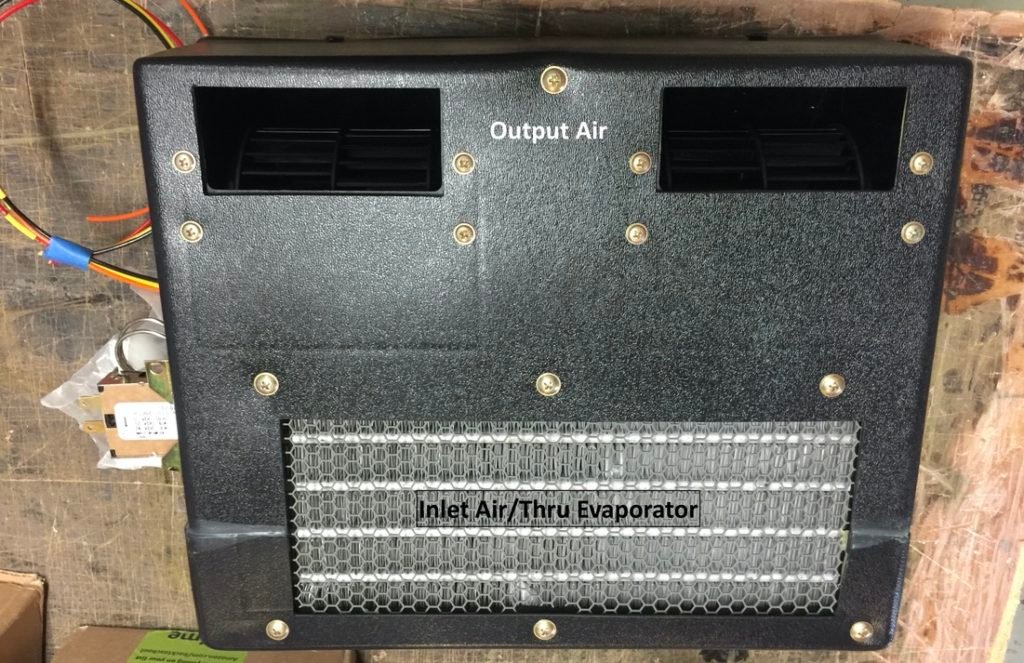
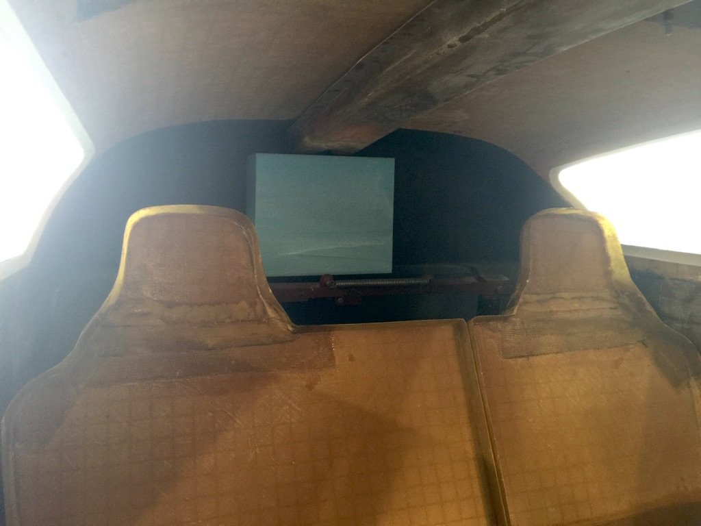
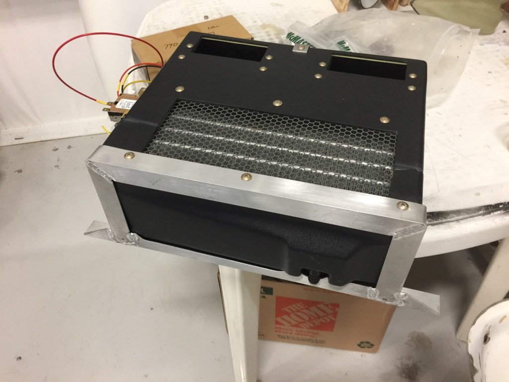
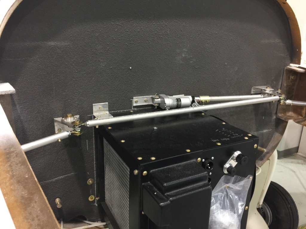
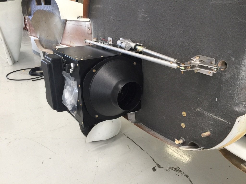
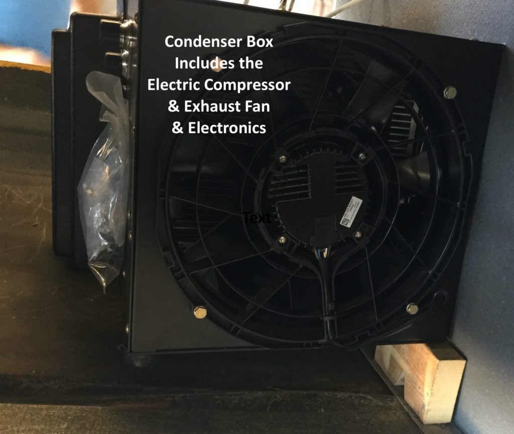
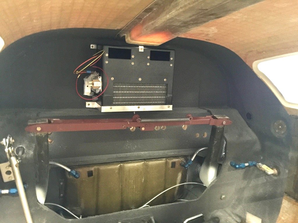
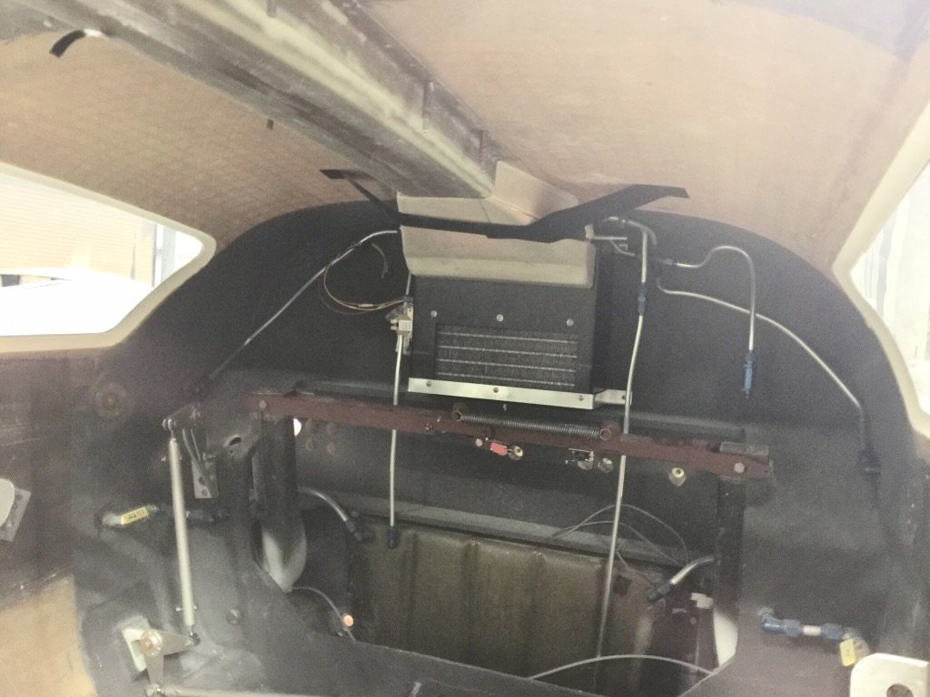
A week or so after I ordered the system, a large shipping box arrived. It was filled with all kinds of “stuff” (a complete AC system, hoses, relays, the works). The first step was to figure out where to place the components and how to mount them. The main items were the evaporator box which also includes the two powerful fans. These are pictured on the right). And then the hot box which contains the condenser, compressor motor, main electronics controller board, and the big cooling fan (pictured further down).
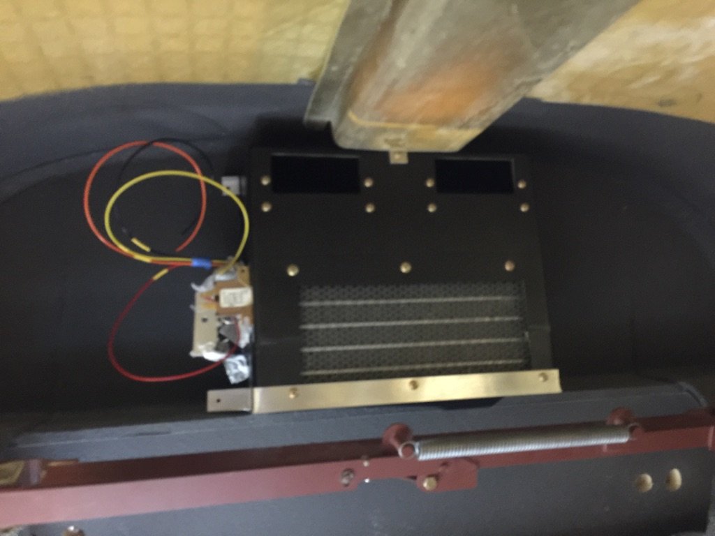
Once I determined that the condenser would fit in the aft top of the cabin (just barely – but the ideal location), I set about making the mounting brackets. I wanted to make the system easily serviceable (read: removable), and Scott supplied angle aluminum from his “stash”, and offered suggestions with the design. His welder, Tyrone, tacked the pieces together as he was competent with welding aluminum.
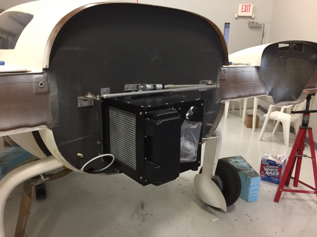
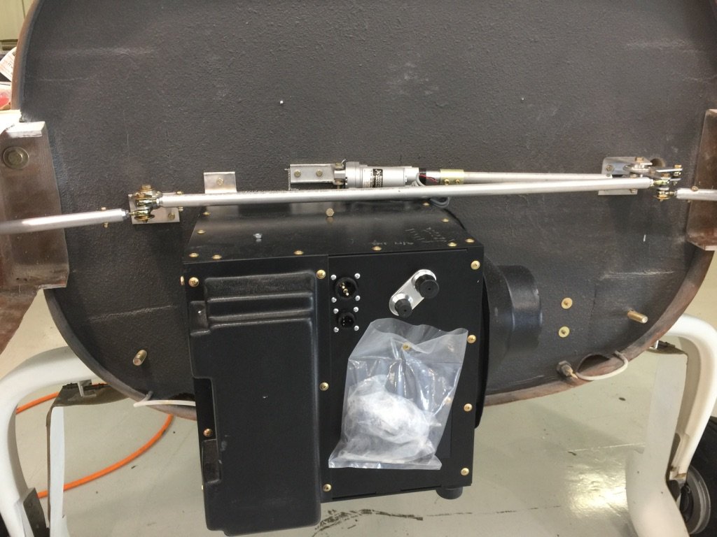
The big item for mounting was the “hot box”. There were two ways to order the system, as individual components or all in one well engineered and designed hot box. While at Oshkosh, John Strain, Flight Line AC, and I had discussed the best solution for the V-Twin. We inspected the Twin at the show, and John recommended the hot box.
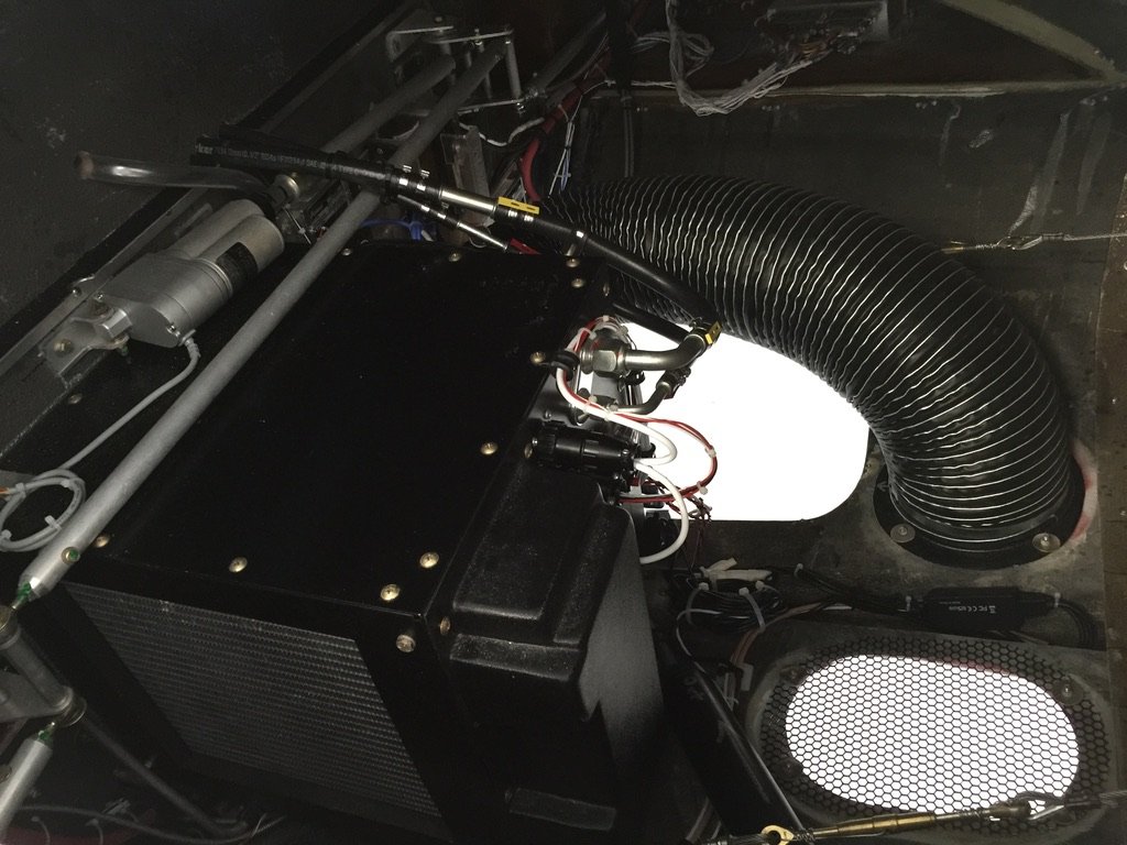
I realize the hot box looks big. Oh, yeah. But it turns out that a lot of the space inside the aluminum box is just air. The size is dictated by the evaporator (on the left) and the exhaust fan (on the right). Between those two large items (necessary for adequate cooling in a cabin of this size) are the electric compressor motor and the electronic components.
One of the problems that builders have experienced is early failure of their compressor motors due to inadequate cooling. In this setup, John guarantees sufficient cooling air flow for the the compressor motor, the evaporator, the electronics, and the exhaust fan. But the most important item on that list is the electric compressor motor. It gets hot, so it requires a cooling air flow.
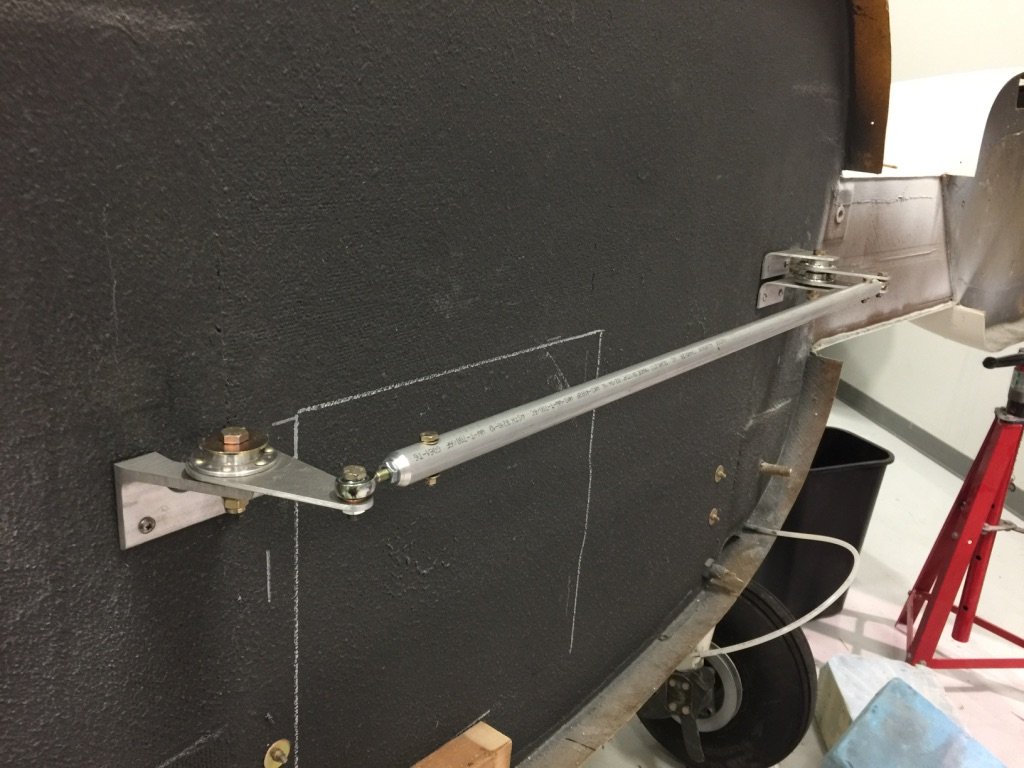
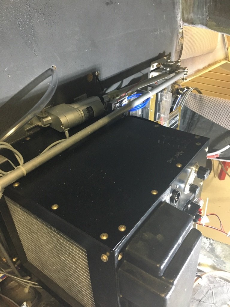
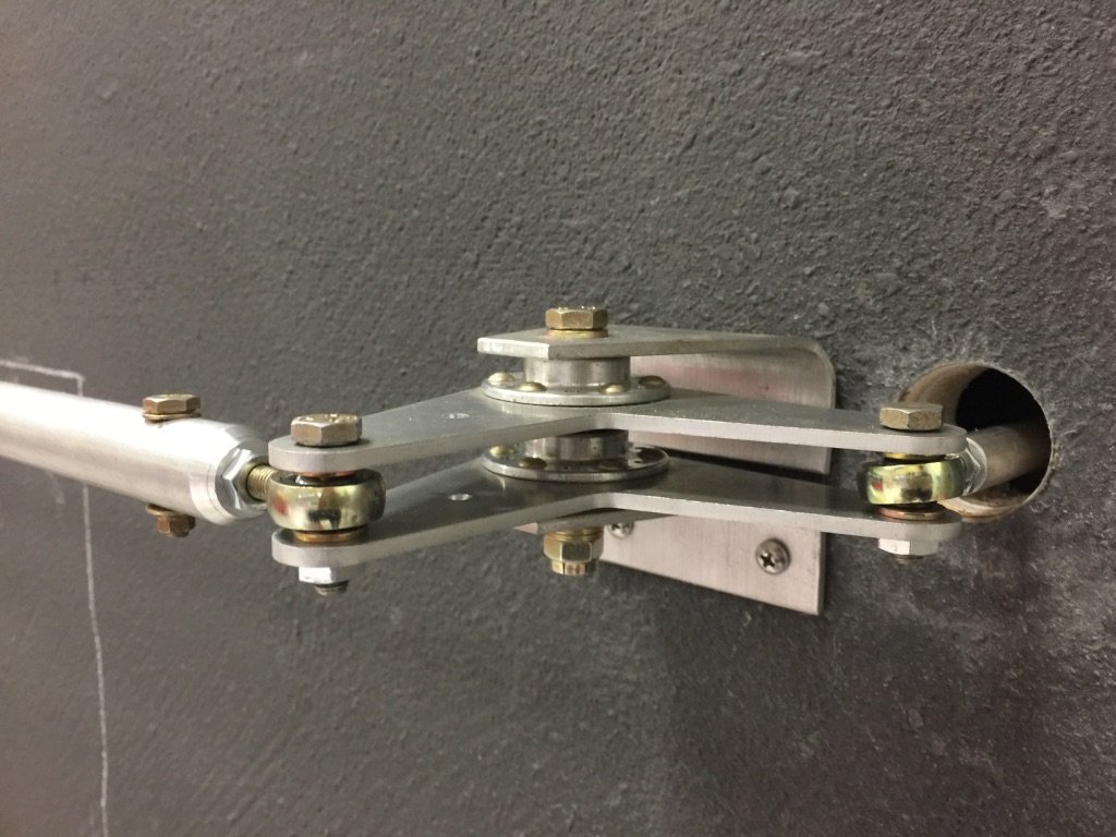
As the project unfolded, there were numerous issues to resolve, but I just tackled each of them, one at a time. Once a decision was made on the hot box location, custom mounts had to be made, and installed. This location then dictated moving the aileron control rods a few inches higher. This cascaded throughout the linkages, but it all works perfectly. I also had to modify the baggage compartment floorboards to accommodate the freon lines, and I had to create a new system for mounting electrical components in the tail cone as the now, usual spots, were no longer available.
This also necessitated moving the aileron trim location just a little, but, luckily, there was adequate space for this.
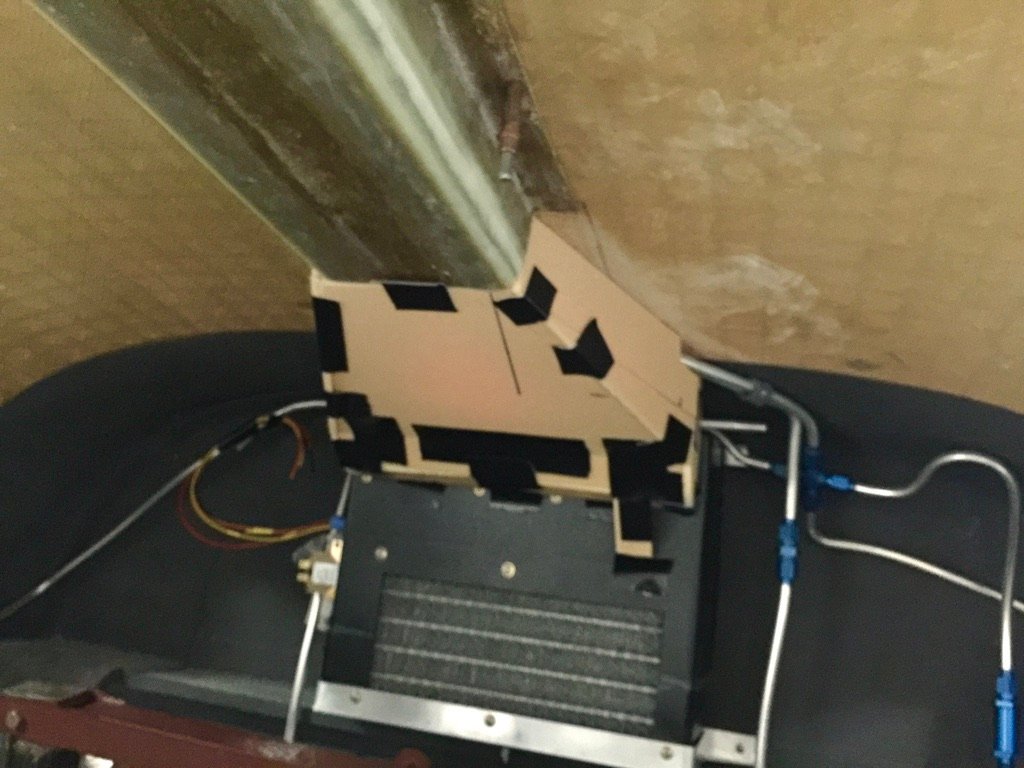
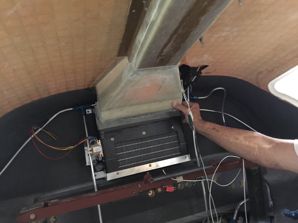
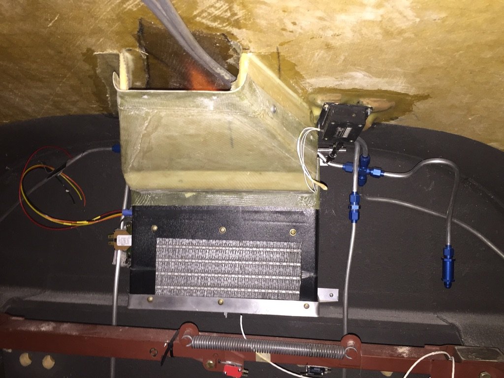
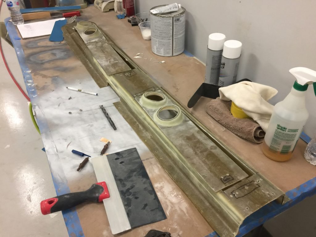
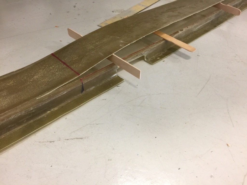
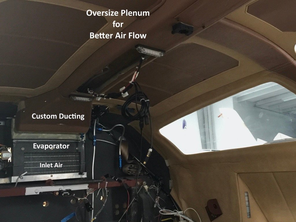
I needed an “adapter ducting” to transition the cooling evaporator air to the overhead plenum. Another local guy that I already mentioned, Ueli, wanted to help, so we worked together to create that ducting. I also wanted an electrically operated flapper, so Ueli used the parts and design that I supplied, and he mounted these for me. This allows for recirculated air only (which I reasoned would maximize cooling), or outside air only (when ac wasn’t needed), or a combination of each. When I installed the drain tube for the evaporator, I observed that I would also need an additional drain tube for this “transition” ducting, so I designed and installed that one Sunday afternoon. Because the evaporator was placed in this location (as I said, just perfect for this application), I had to reroute and redesign the layout of the fuel vents, but I still routed the vent forward and inside the overhead plenum for maximum effect.
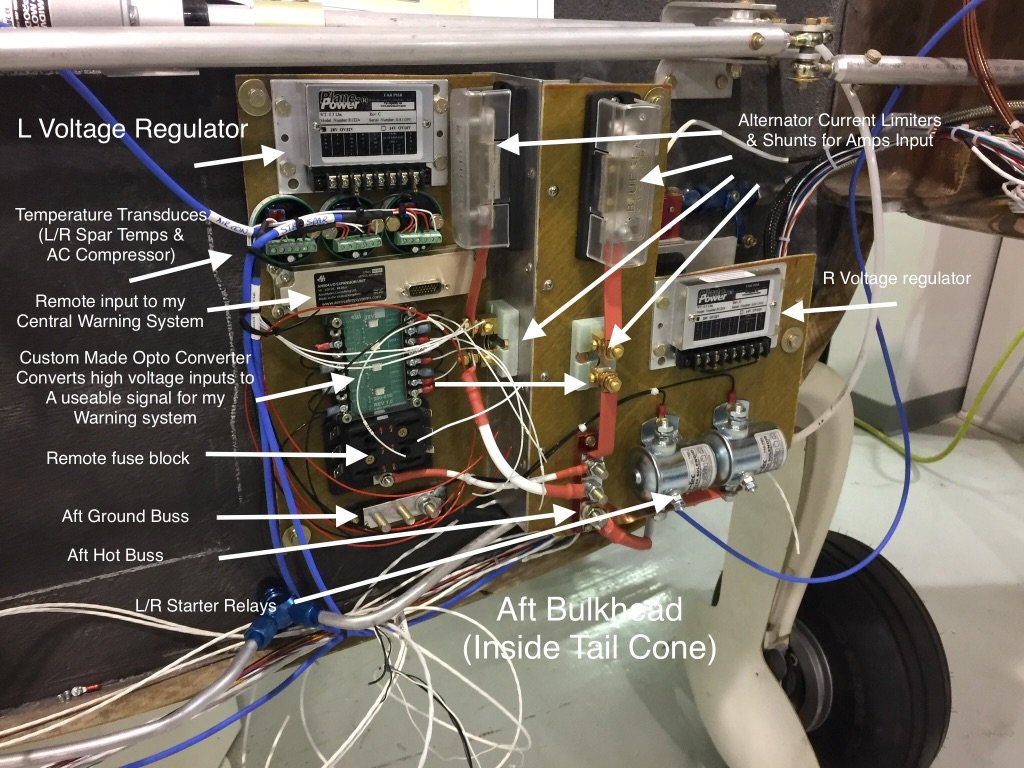
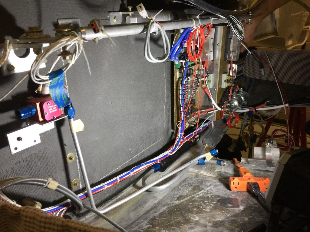
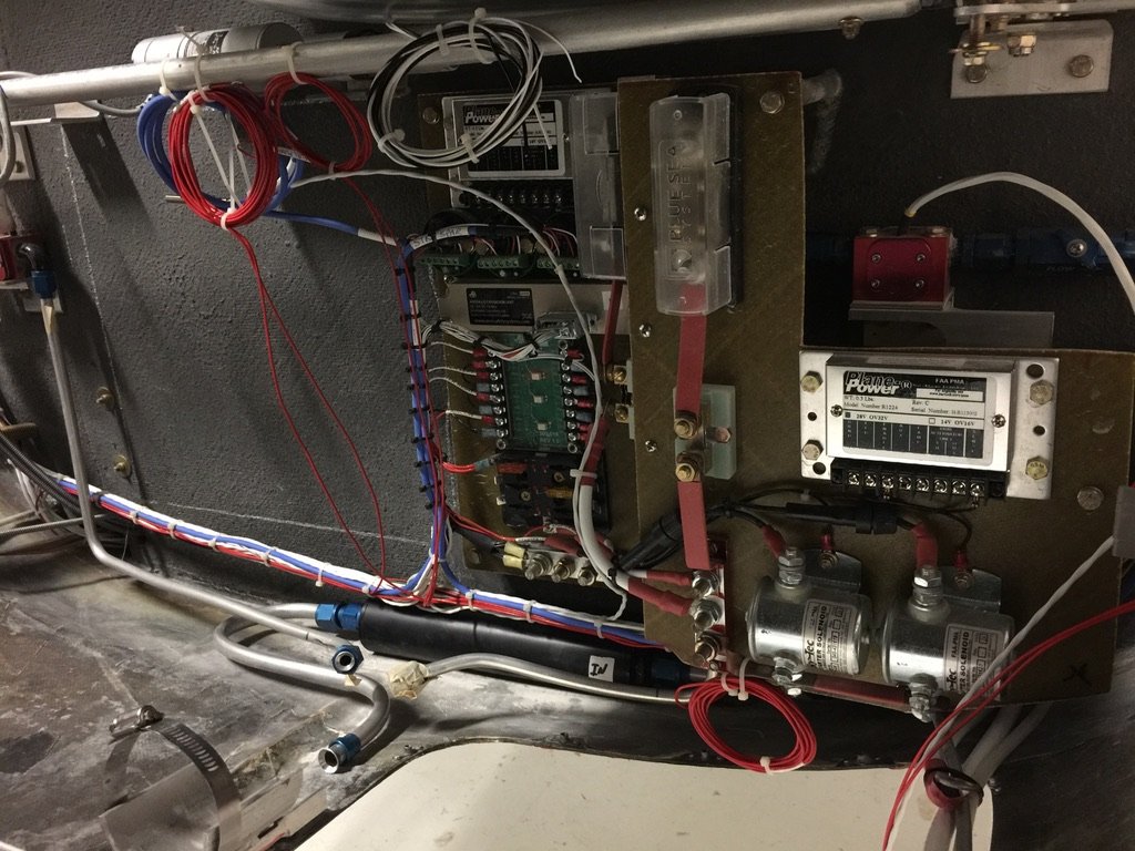
Here is the new mounting system that I created for the electrical components in the tail cone area. As you can see, there is quite a lot that needs to be mounted in this location. But it all fits on my two offset panels. They had to be offset to accommodate the right engine fuel line and emergency fuel shutoff. The only items placed elsewhere were the two GEA24 engine monitors and their associated engine sensors – three each. They are all mounted in the wing roots, easily accessible from inside the tail cone area. This was just another “design” problem. I made the mounting boards to fit the available space, then laid out the components until I had a logical and reasonable organization.
You can see here that I had to design the new component mounting system, wiring, plumbing, and ailerons around the hot box location. It all came to together quite nicely. It’s accessible and, therefore, serviceable.
One side note is that the fuel flow transducers (red cubes) were later moved to the engine compartment as they didn’t function well in these locations.
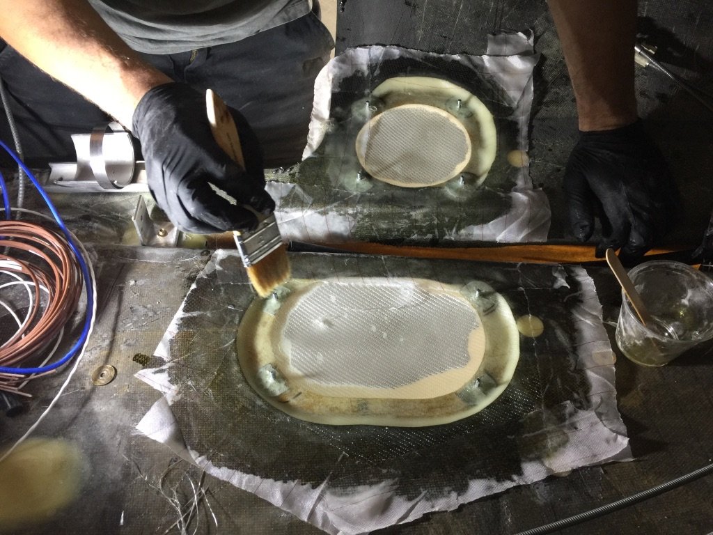
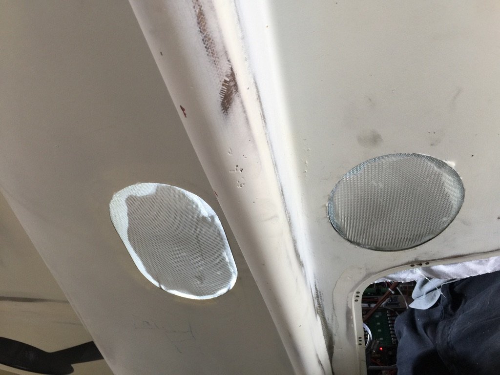
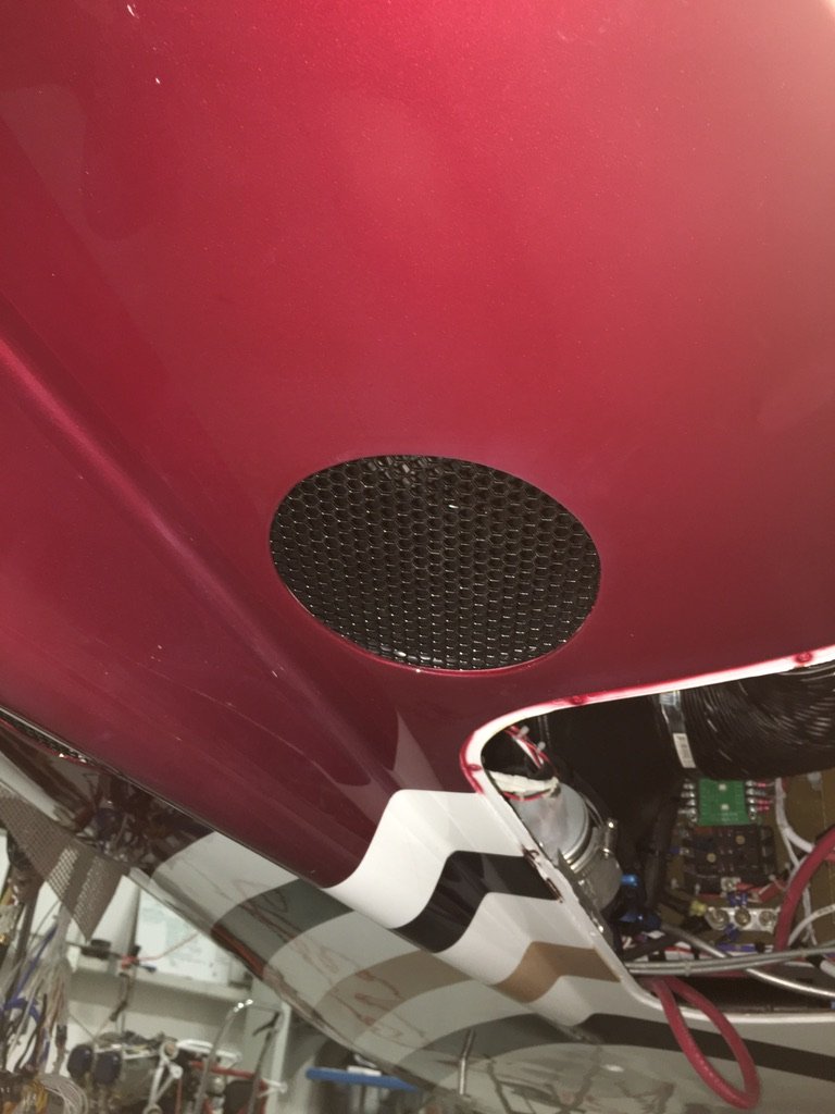
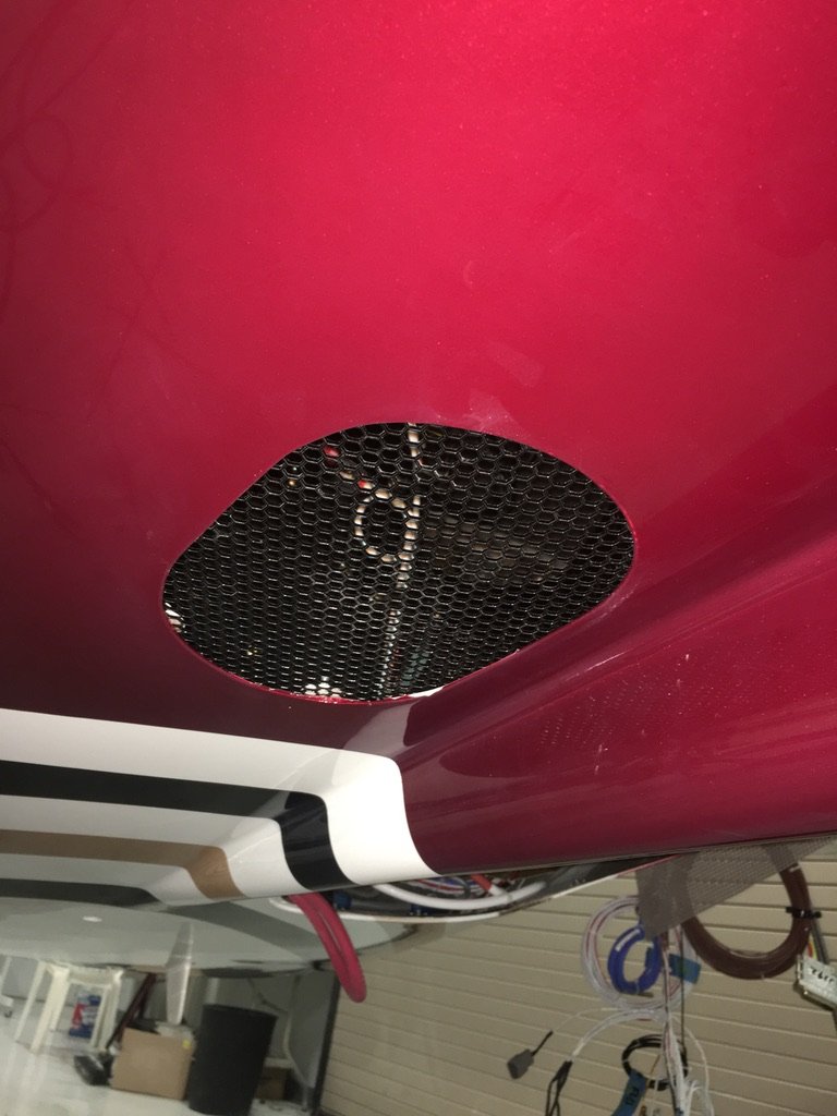
There were still some remaining steps to get this system install completed: creating sources for inlet and outlet air, finishing up the modifications to the overhead plenum, installing the cabin temp sensor, digital ac controller in the console, all the wiring, making/installing the Freon hoses, and, finally, charging the system. As you can see above, I created two holes in the bottom of the tail cone. The larger one is for inlet air. The smaller one is for the hot exhaust air (routed overboard via a large, 6″ flexible tube). I beefed up these holes for strength, then I installed a powder coated aluminum mesh with a nice, honeycomb look. I got the mesh from a company that makes aftermarket grills for cars. They had a section on their web site labeled “Junk Pile”. 🙂
One more thing that I added to the ac system is a temperature probe for the hot exhaust air as it exits the condenser exhaust fan. I placed it in the plastic exhaust shroud that connects to the 6″ hose. I did this because, with the system located almost completely in the tail cone, I want some reassurance that things were going well “in the back”. 🙂 I want to know that the system is not overheating, or worse. I like the extra measure of reassurance. This probe is connected to my AH500 central warning system.
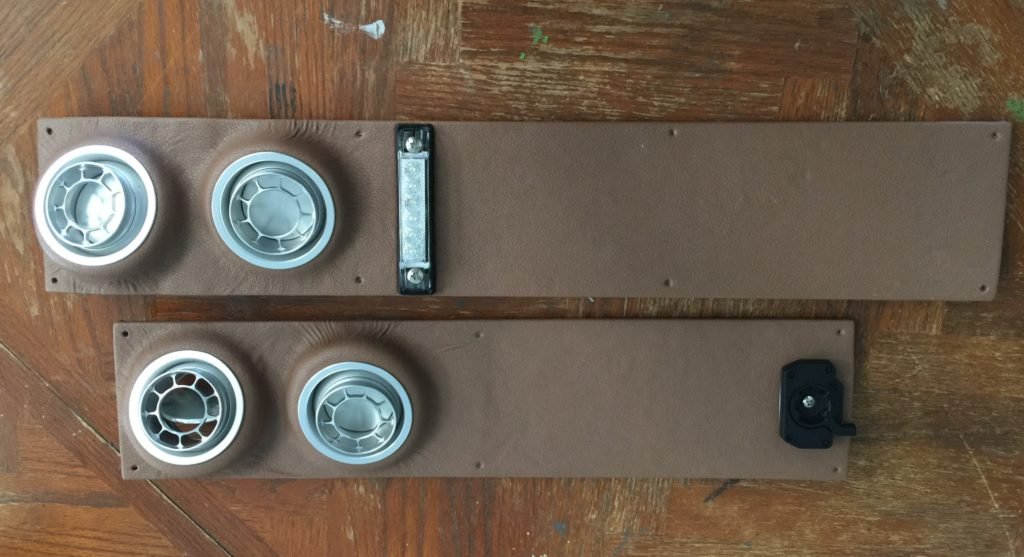
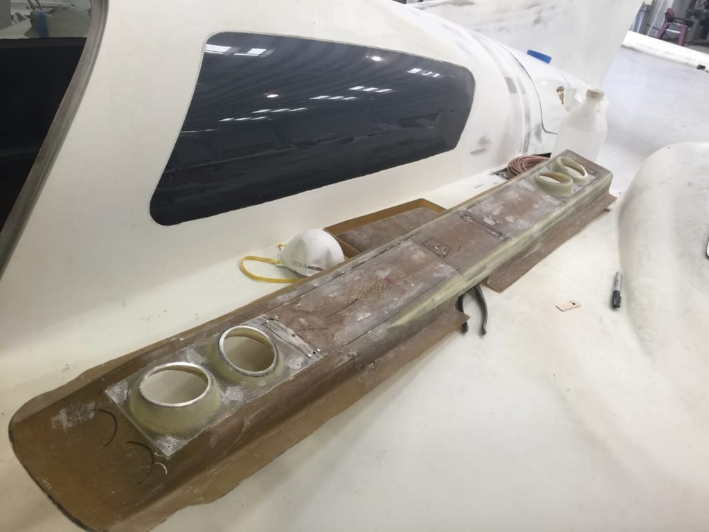
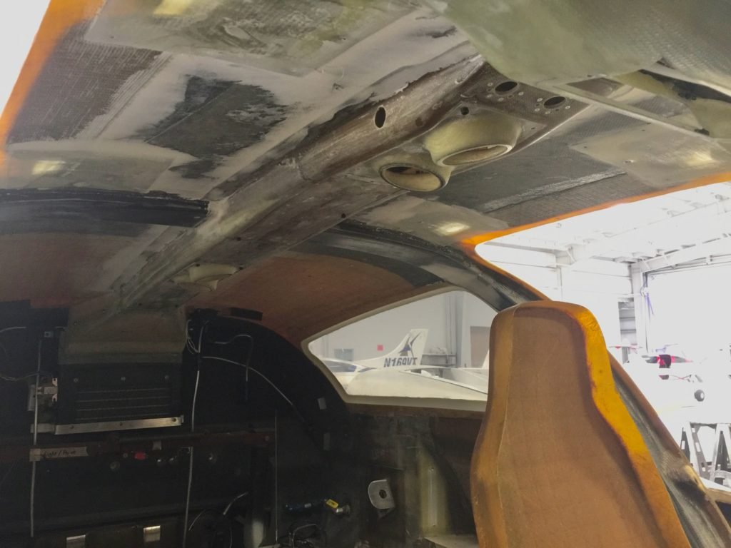
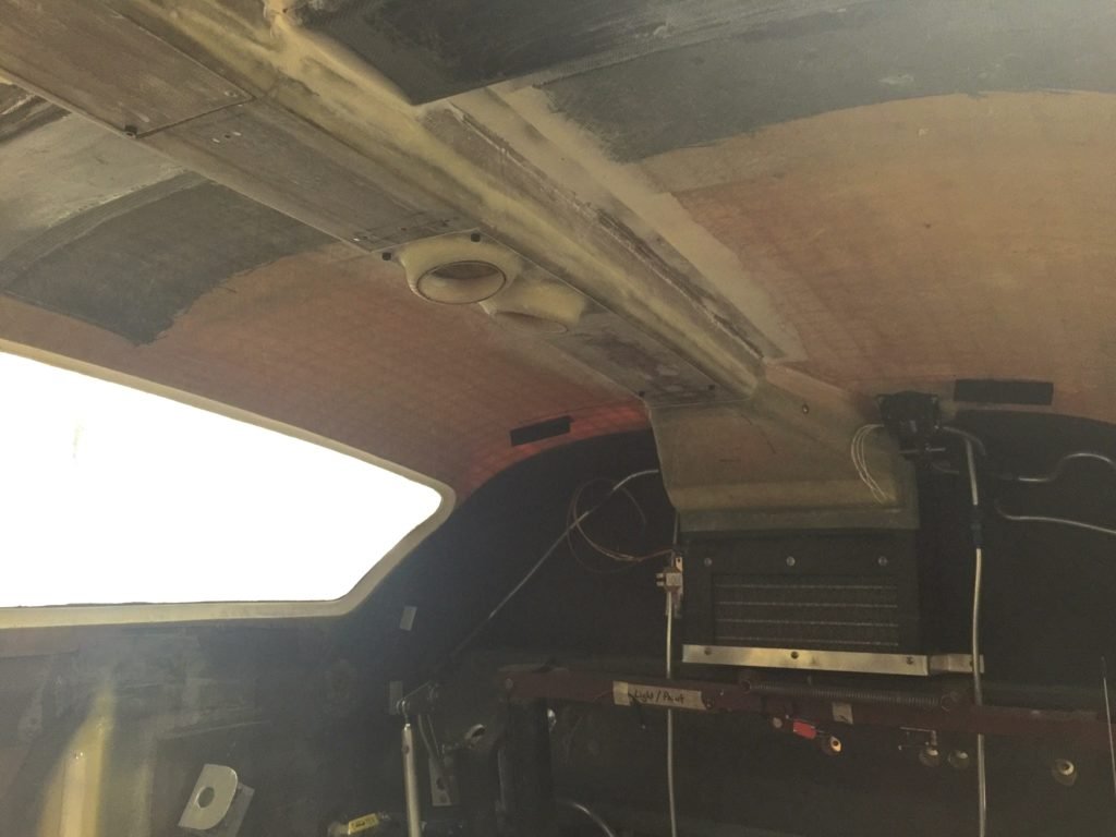
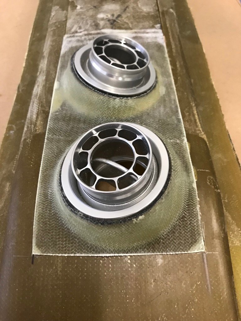
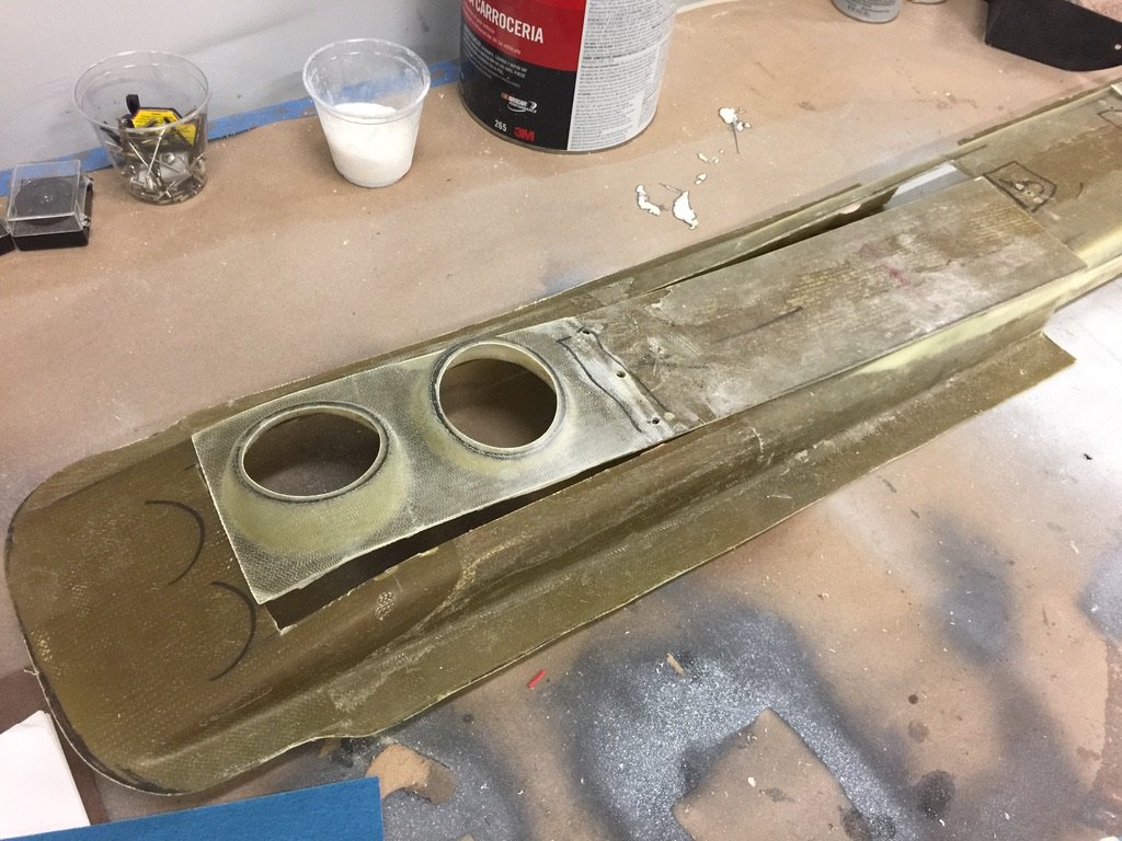
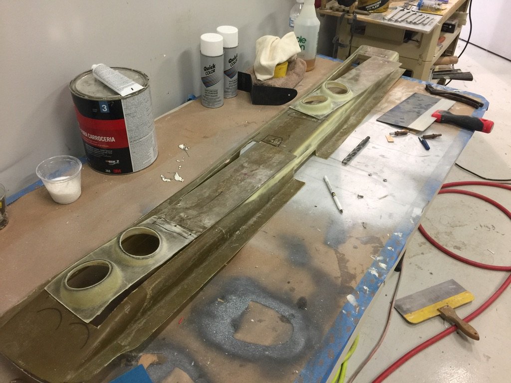
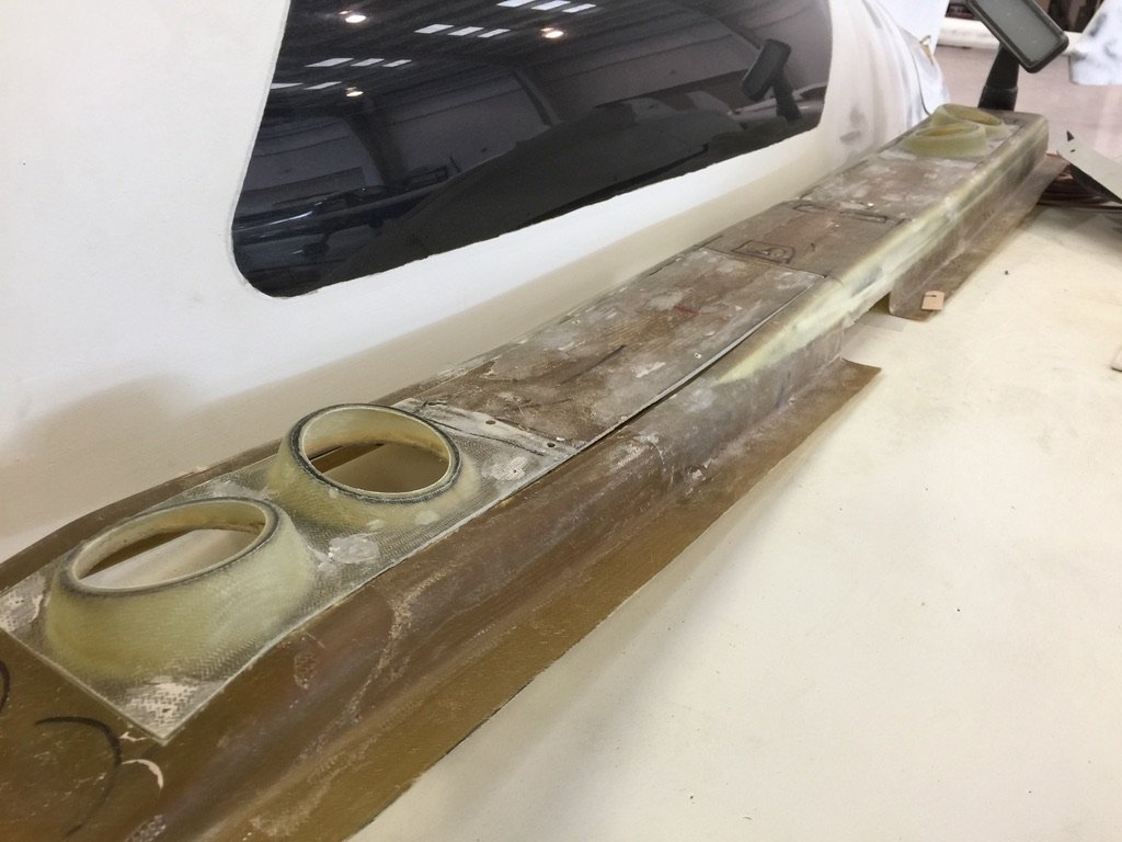
As I mentioned earlier, I enlarged the overhead plenum for adequate cooling airflow. For this be effective like I wanted, I also used larger than normal eyeball vents. The result? Excellent air flow!
The problem with the “normal” plenum is the reduced area due to the carbon fiber fuselage and door frame strengthening layups. While this restricts the airflow, it’s not a problem for outside, vented air as there is more than enough flow. Instead, the problem is for the ac evaporator fans. They need to be able to push enough cool air all the way forward. Hence, the need to enlarge the plenum. Once the plenum is opened up to clear this cross bar, then I tapered it back down to it’s original shape so that it tucks in nicely, not interfering with the overhead switch panel. It turned out great. I am very happy with it.
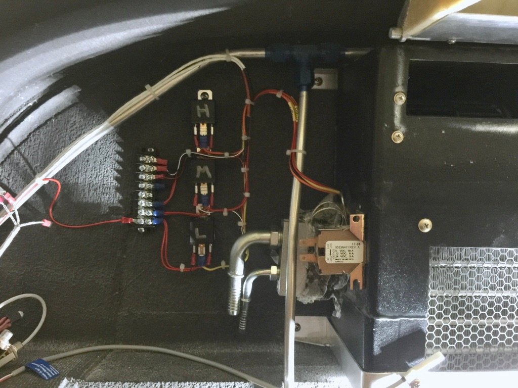
Wiring the evaporator: three speed fan (three relays), temp sensor, etc.

This is how I ended up wiring everything. There was basically three steps to wiring up the ac. First, was wiring the hot box in the back. The three pin connector brought in the 28 volt power lines, 8 gauge, from the aft 28 volt buss. The other connector was to communicate with the digital controller and the evaporator thermostat. Second was power to the fan relays and connecting to the return air thermister. Third was connecting up the digital controller in the center console.
Note that my wife and I used the air conditioner on every single leg on the way home from Florida to California. This happened to be during a spring time heat wave. We were really glad to have it, and this turned out to be a very successful operational test. 🙂
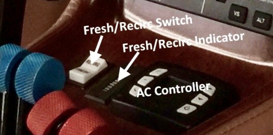
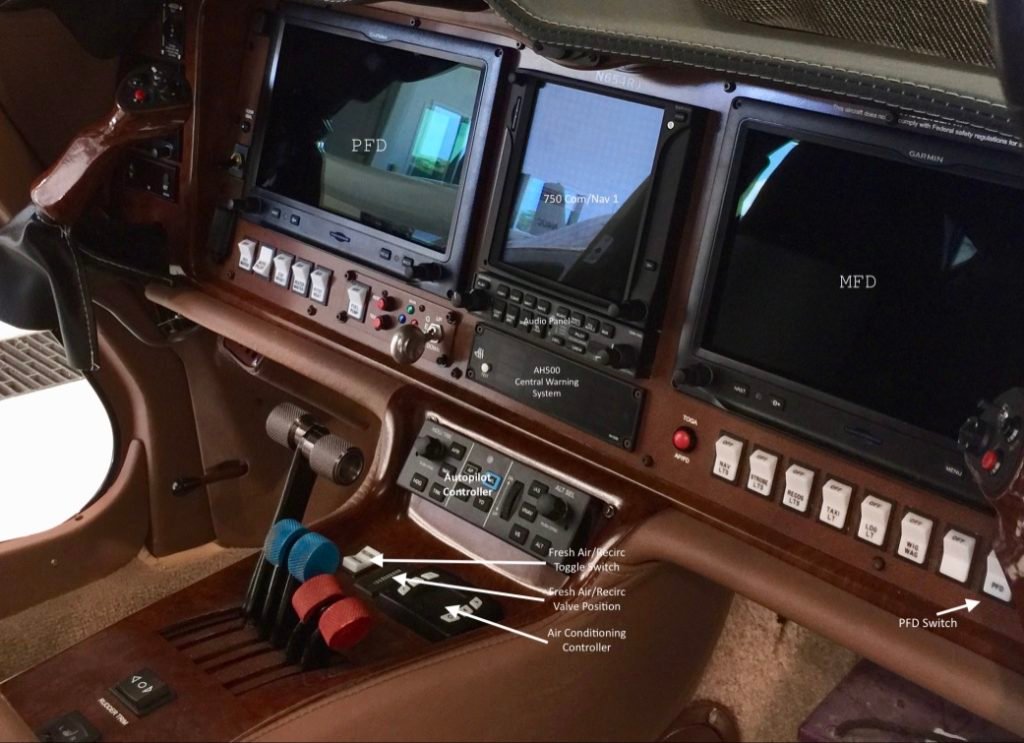
I control the fresh air/recirc flapper with this spring loaded toggle switch. I use a Ray Allen actuator and a Ray Allen indicator which displays the flapper position. The ac controller features 3 fan speeds. But if you need cooling, you can switch to AC mode. The fan can be used to recirculate air when the ac is off, as well as, boost the outside air when on the ground. Very handy!
If you got this far, you will no doubt agree that the air conditioner was a big project.
There were lots of considerations. Where to put things. How to mount them. Wiring. Ducting. And so on.
Finally, this air conditioning system works so well that when I was flying in the hot Florida climate, I turned it on right after engine start and closed the cabin doors!
The cabin quickly cooled, and it was quite pleasant having that nice, cool air blowing out of those large eyeball vents.
So, yes, all this hard work and effort was worth it!

